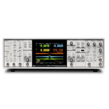
DISCONTINUED SRS SR830 DSP Lock-in Amplifier, 102kHz

After several decades the groundbreaking SR830 DSP lock-in amplifier has been discontinued due to parts availability issues. The replacement SR860 and SR865A lock-in amplifiers are now the default choice for customers requiring a self-contained, stand-alone and class-leading lock-in amplifier solution.
- 1 mHz to 102 kHz frequency range
- Magnitude & phase display
- 100 dB dynamic reserve without pre-filtering
- Auto-gain, phase and reserve
- Time constants from 10 µs to 30 ks
- 6, 12, 18, 24 dB/oct rolloff
- Harmonic detection (2F, 3F, ..., nF)
- Standard GPIB and RS-232 interfaces
Lambda Exclusive Promotion:
Additional 12 months warranty for free (2 years total) via our UK Service Centre.
The Stanford Research Systems SR810 and SR830 are part of the SRS family of DSP lock-in amplifiers. Using DSP technology pioneered by SRS, these units deliver unmatched digital performance at a price below that of most conventional lock in amplifiers. While sharing most features and specifications, the SR810 and SR830 differ in a few important respects. In particular, the SR830 has two data displays, allowing the simultaneous display of X and Y, or R and Θ, while the SR810 has only a single data display (although the SR810 allows access to all parameters, including X,Y, R and Θ over the computer interfaces.)
Digital Demodulator
The heart of the SR810 and SR830, is the demodulator, which multiplies the input signal by the reference signal and filters the result. The DSP processor is capable of performing 16 million 24-bit multiplications and additions every second. In the case of the SR810 and SR830 the input is digitised at 256 kHz by a precision 18-bit A/D convertor. It is this digital demodulation technique which is at the root of so many of the SR810 and SR830's performance advantages. The digital technique eliminates the drift, distortion, and aging that are inherent in all analog demodulation designs and allow the SR810 and SR830 to achieve up to 100 dB of dynamic reserve. Dynamic reserve, a key figure of merit for lock-in amplifiers, is a specification often mentioned by lock-in manufacturers without offering a precise definition.
It is always important to keep in mind that many manufacturers do not use this conservative definition of dynamic reserve. The SR810 and SR830 both have up to 100 dB of true available dynamic reserve.
Digital Filtering
The digital signal processor also handles the task of output filtering, time constants from 10 µs to 30,000 s to be selected, with a choice of 6, 12, 18 and even 24 dB/oct filter rolloff. For low frequency measurements (below 200 Hz), synchronous filters can be engaged to notch out multiples of the reference frequency.
Digital Phase Shifting
The clumsy analog phase shifting circuits found in conventional lock-ins have been replaced in the SR810 and SR830 with a precise numerical calculation performed by the DSP processor. This allows phase to be measured with 0.01° resolution and the X and Y outputs to be orthogonal to 0.001°. This represents a significant improvement over analog instruments.
Frequency Synthesiser
The built-in direct digital synthesis (DDS) source generates a very low distortion (-80 dBc) reference signal. Single frequency sinewaves can be generated from 1 mHz to 102 kHz with 4 1/2 digits of frequency resolution. Both frequency and amplitude can be set from the front panel or from a computer.
Easy Operation
The SR830 has two data displays which can be quickly configured to show X, Y, R, Θ, Xnoise, Ynoise or either of the two aux inputs. The SR810 has a single data display. Both the SR810 and SR830 have an additional LED display which can be set to display the reference frequency, phase, or amplitude.
Input Channel
The SR810 and SR830 both have a fully differential input with only 6 nV/√Hz of input noise at 1 kHz and an input impedance of 10 MΩ. The minimum full scale input voltage is 2nV, the lock-ins both include a current input amplifier with a switchable gain of 106 or 108 Volts/Amp. Line (50 Hz or 60 Hz) and 2x line filters are included to reduce line related interference, and the SR810's and SR830's digital architecture eliminate the need for input bandpass filters. Digital design makes it possible to obtain 100 dB of dynamic reserve.
Analog Inputs and Outputs
Both instruments have a user-defined output for measuring X, R, X-noise, Aux1, Aux 2 or the ratio of the input signal to an external voltage. The SR830 has a second user-defined output that measures Y, Θ, Y-noise, Aux 3, Aux 4 or ratio. The SR810 and SR830 both have X and Y analog outputs (rear panel) that are updated at 256 kHz. Four auxiliary 16-bit inputs are provided for general purpose use and can be read from the front panel or the computer interface. Four programmable 16-bit outputs provide voltages from -10.5 V to +10.5 V and can be set via the front panel or computer interfaces.
Internal Memory
The SR810 has an 8,000 point memory buffer for recording the time history of a measurement at rates up to 512 samples/sec. The SR830 has two 16,000 point buffers to simultaneously record two measurements, like R and Θ. Data is transferred from the buffers using the computer interfaces. A trigger input is also provided to externally synchronise data recording.
Additional Information
| Max. Frequency | 100kHz |
|---|---|
| Type | DSP |
SRS SR830 DSP Lock-in Amplifier, 102kHz
| Signal Channel | |
| Voltage inputs | Single-ended or differential |
| Sensitivity | 2 nV to 1 V |
| Current input | 106 or 108 V/A |
| Input impedance: | |
| Voltage input | 10 MΩ + 25 pF, AC or DC coupled |
| Current input | 1 kΩ to virtual ground |
| Gain accuracy | ±1 % (±0.2 % typ.) |
| Noise | 6 nV/√Hz at 1 kHz |
| 0.13 pA/√Hz at 1 kHz (106] V/A) | |
| 0.013 pA/√Hz at 100 Hz (108] V/A) | |
| Line filters | 50/60 Hz and 100/120 Hz (Q=4) |
| CMRR | 100 dB at 10 kHz, decreasing by 6 dB/oct above 10 kHz |
| Dynamic reserve | >100 dB (without prefilters) |
| Stability | <5 ppm/°C |
| Reference Channel | |
| Frequency range | 0.001 Hz to 102.4 kHz |
| Reference input | TTL or sine (400 mVpp min.) |
| Input impedance | 1 MΩ, 25 pF |
| Phase resolution | 0.01° front panel,0.008° through computer interfaces |
| Absolute phase error | <1° |
| Relative phase error | <0.001° |
| Orthogonality | 90° ± 0.001° |
| Phase noise: | |
| Int. reference | Synthesized, <0.0001° rms at 1 kHz |
| Ext. reference | 0.005° rms at 1 kHz, 100 ms, 12 dB/oct |
| Phase drift | <0.01°/°C below 10 kHz, |
| <0.1°/°C, 10 kHz to 100 kHz | |
| Harmonic detection | 2F, 3F, ... nF to 102 kHz (n<19,999) |
| Acquisition time | (2 cycles + 5 ms) or 40 ms, whichever is greater |
| Demodulator | |
| Stability: | Digital outputs and display: no drift Analog outputs: <5 ppm/°C for all dynamic reserve settings |
| Digital outputs and display | no drift |
| Analog outputs | |
| Harmonic rejection | -90 dB |
| Time constants | 10 µs to 30 ks (6, 12, 18, 24 dB/oct rolloff). Synchronous filtering available below 200 Hz. |
| Internal Oscillator | |
| Range | 1 mHz to 102 kHz |
| Accuracy | 25 ppm + 30 µHz |
| Frequency resolution | 4½ or 0.1 mHz whichever is greater |
| Distortion | -80 dBc (f < 10 kHz) |
| -70 dBc (f > 10 kHz) at 1 Vrms amplitude | |
| Amplitude | 0.004 to 5 Vrms into 10 kΩ (2 mV resolution), 50 Ω output impedance, 50mA maximum current into 50 Ω |
| Amplitude accuracy | 1% |
| Amplitude stability | 50 ppm/°C |
| Outputs | Sine and TTL (when using an external reference, both outputs are phase locked to the external reference) |
| Sweeps | Linear and log |
| Displays | |
| Channel | 4½-digit LED display with 40-segment LED bar graph. X, R, X-noise, Aux 1 or Aux 2. The display can also be any of these quantities divided by Aux 1 or Aux 2. |
| Offset | X, Y, R can be offset up to ±105 % of full scale. |
| Expand | X, Y, R can be expanded by 10× or 100×. |
| Reference | 64½-digit LED display |
| Inputs and Outputs | |
| CH1 output | ±10 V output of X, R, X-noise, Aux 1 or Aux 2. Updated at 512 Hz. |
| X, Y outputs | In-phase and quadrature components |
| Rear panel | ±10 V, updated at 256 kHz |
| Aux. A/D inputs | 4 BNC inputs, 1 mV resolution, ±10 V, sampled at 512 Hz |
| Aux. D/A outputs | 4 BNC outputs, 1 mV resolution, ±10 V |
| Sine out | Internal oscillator analog output |
| TTL out | Internal oscillator TTL output |
| Data buffer | 8k point buffer. Data is recorded at rates to 512 Hz and read through the computer interfaces |
| Trigger In (TTL)) | Trigger synchronizes data recording |
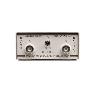
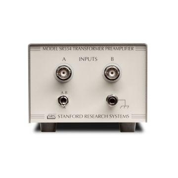
| Remote pre-amp | Provides power to the optional SR550, SR552 and SR554 preamps |
| General | |
| Interfaces | IEEE-488.2 and RS-232 interfaces standard. All instrument functions can be controlled and read through IEEE-488.2 or RS-232 interfaces. |
| Power | 40 W, 100/120/220/240 VAC, 50/60 Hz |
| Dimensions | 17" × 5.25" × 19.5" (WHL) |
| Weight | 23 lbs. |
| Warranty | One year parts and labor on defects in materials and workmanship |
![]() Stanford Research Systems SR830 Series datasheet
Stanford Research Systems SR830 Series datasheet
![]() Stanford Research Systems SR830 user manual
Stanford Research Systems SR830 user manual
![]() Why buying from Lambda makes sense
Why buying from Lambda makes sense
| Photo | Product | Max. Frequency | Type | Price | |
|---|---|---|---|---|---|
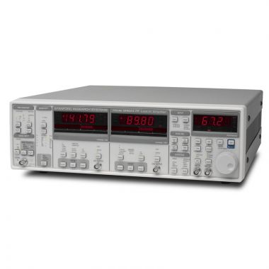
 | SRS SR860 DSP Lock-in Amplifier, 500 kHz | 500kHz | DSP | 6,416.00 | |
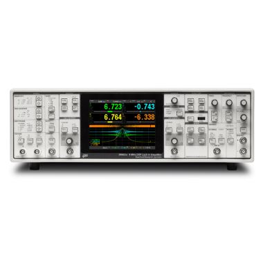 | SRS SR865A DSP Lock-In Amplifier, 4MHz | 4MHz | DSP | 9,039.00 | |
 | SRS SR844 DSP RF Lock-in Amplifier, 200MHz | 200MHz | DSP | > | |
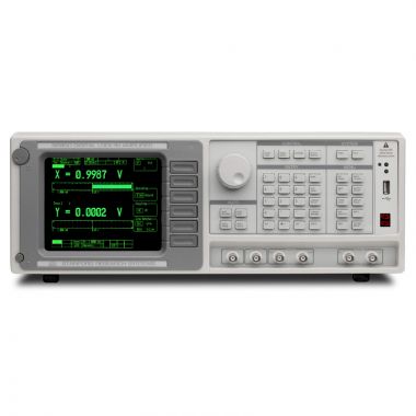 | SRS SR850 DSP Lock-in Amplifier, 102kHz | 100kHz | DSP | > | |
 | SRS SR2124 - 200 kHz Analogue/Analog Lock-in Amplifier | 200kHz | Analogue | > | |
 | SRS SX199 Optical Interface Controller | - | - | > | |
 | DISCONTINUED SRS SR530 Analogue Lock-in Amplifier, 100kHz | 100kHz | Analogue | > | |
 | SRS SR510 Analogue Lock-in Amplifier, 100kHz | 100kHz | Analogue | > |