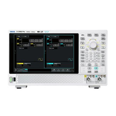
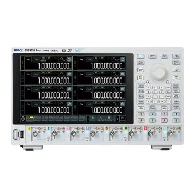
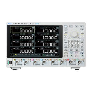
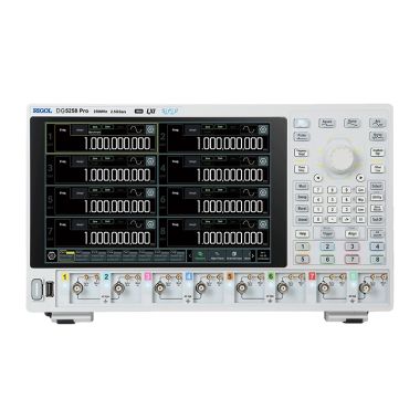
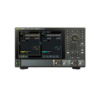
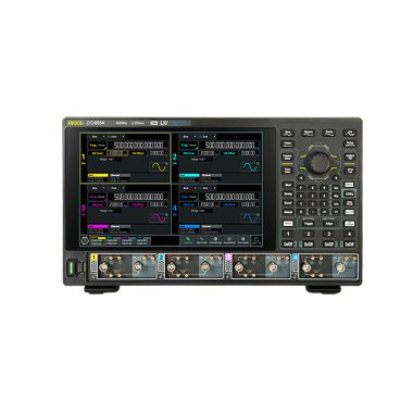
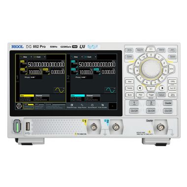
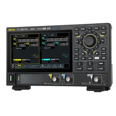
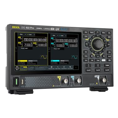
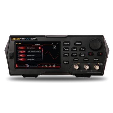
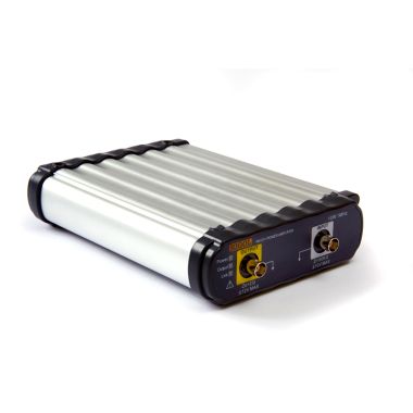
Rigol DG6104 1GHz 2.5GSa/s 4 Channel Function/Arbitrary Waveform Generator

The RIGOL DG6104 is a high-performance, 4-channel flagship signal source designed to meet the rigorous demands of high-speed digital testing, power semiconductor characterisation, and advanced scientific research.
- 1GHz Bandwidth
- 4 High-voltage differential channels
- 2.5 GSa/s Sample rate
- 16-Bit Vertical resolution
- Fully Isolated channels
- 350ps Square wave rise time
- 256Mpts (512Mpts Optional) Memory depth
- Advanced modulation (IQ, PRBS, Pattern, Multi-tone, Multi-pulse)
- Internal complex sequencer
- 10.1 Inch display
Featuring 16-bit vertical resolution and a 1 GHz bandwidth, the DG6104 provides a powerful, all-in-one platform that integrates the capabilities of a function generator, arbitrary waveform generator (AWG), pulse generator, and digital modulator.
Native High-Voltage Differential Direct Drive
The DG6104 features a 4-channel high-voltage differential direct-drive architecture. This technology allows the instrument to output differential signals up to 20 Vpp (into High-Z) without the need for external power amplifiers or baluns, significantly simplifying the test chain for SiC/GaN gate drive simulations.
350 ps Fast-Edge Square Waves
Engineered for time-domain precision, the DG6104 delivers square waves up to 300 MHz with a typical transition time of 350 ps. This "gold-standard" edge performance makes it an ideal clock source for verifying high-speed digital interfaces and conducting setup/hold time analysis.
Full Channel Electrical Isolation
To ensure clean signal delivery and protect sensitive Devices Under Test (DUT), all channels are electrically isolated. This design eliminates ground loops and crosstalk, facilitating safe and accurate floating ground measurements in complex power systems.
Massive 512 Mpts Arbitrary Memory
With an optional memory depth of up to 512 Mpts per channel, the DG6104 can store and reproduce long-period, non-repetitive real-world waveforms. This capacity is essential for simulating complex environments such as radar, sonar, and automotive serial buses.
Comprehensive Integrated Signal Library
The DG6104 includes a standard suite of advanced signal generation modes, including IQ modulation, PRBS patterns, multi-pulse, multi-tone, and sequence logic. These built-in templates allow for rapid configuration of communication signals and logic verification without requiring external PC software.
Advanced Operating Modes
The instrument supports three distinct output modes to optimise performance for specific test requirements:
- HBW (High Bandwidth): Provides the maximum 1 GHz frequency range for differential outputs.
- AMP (High Amplitude): Delivers high-voltage differential signals up to 20 Vpp for power semiconductor testing.
- SND (Single-Ended): Standard single-ended BNC output for general-purpose lab applications.
Connectivity and Remote Operation
- Interfaces: Includes LAN (LXI-C compliant), USB 3.0 (Host & Device), and HDMI for external monitor support.
- Web Control: Standard Web Control functionality allows users to mirror and operate the instrument interface directly through a web browser, facilitating remote collaboration and automated testing.
Additional Information
| No. of Channels | 4 |
|---|---|
| Signal Generator Type | Arbitrary |
| Bandwidth MHz | 1000 |
| Bit Resolution | 16 |
| Model | DG6052 | DG6054 | DG6102 | DG6104 |
| No of Channels | 2 | 4 | 2 | 4 |
| Output type | SND/HBW/AMP | |||
| Max Frequency | 500 MHz | 1 GHz | ||
| Max Sample Rate | 2.5 GSa/s | |||
| Vertical Resolution | 16 Bits | |||
| Memory Depth | 256 Mpts/CH (standard), 512 Mpts/CH (optional) | |||
| Output Mode | Continuous, Modulation, Sweep, Burst, Advanced | |||
| Continuous | Sine, Square, Ramp, Pulse, Noise, Arb, DC, Harmonic | |||
| Modulation | AM, FM, PM, SUM, ASK, FSK, PSK, PWM | |||
| Sweep | Linear, Log, Step | |||
| Burst | N-cycle, Gated | |||
| Advanced | Sequence, Pattern, Arb, PRBS, Multi-pulse, Multi-tone, IQ | |||
| SND (BNC Output) | ||||
| Amplitude Range (into 50 Ohm) | ≤100 MHz: 1 mVpp to 10 Vpp | |||
| ≤250 MHz: 1 mVpp to 5 Vpp | ||||
| ≤350 MHz: 1 mVpp to 2 Vpp | ||||
| ≤500 MHz: 1 mVpp to 1 Vpp | ||||
| Amplitude Accuracy | ±(1% of the setting + 1 mVpp) | |||
| Amplitude Resolution | 0.1 mVpp, 0.1 mVrms, 1 mV, 0.1 dBm or 4 digits | |||
| (whichever is lower) | ||||
| Units | Vpp, Vrms, dBm, V (high level and low level) | |||
| Offset Range | ±5 Vpk (ac + dc) | |||
| Offset Accuracy | ±(1% of |setting| +1 mV + 0.5% of the amplitude (Vpp)) | |||
| Offset Resolution | 1 mV or 4 digits | |||
| Output Impedance | 50 Ω ± 1% | |||
| Load Impedance Setting | Load (adjustable from 1 Ω to 10 kΩ), High Z | |||
| AMP (BNC Output) | ||||
| Amplitude Range (into 50 Ohm) | ≤100 MHz: 2 mVpp to 20 Vpp | |||
| ≤250 MHz: 2 mVpp to 10 Vpp | ||||
| ≤350 MHz: 2 mVpp to 4 Vpp | ||||
| ≤500 MHz: 2 mVpp to 2 Vpp | ||||
| Amplitude Accuracy | ±(2% of the setting + 2 mVpp) | |||
| Amplitude Resolution | 0.1 mVpp, 0.1 mVrms, 1 mV, 0.1 dBm or 4 digits | |||
| (whichever is lower) | ||||
| Units | Vpp, Vrms, dBm, V | |||
| Offset Range | ±5 Vpk (ac + dc) | |||
| Offset Accuracy | ±(1% of |setting| +1 mV + 0.5% of the amplitude (Vpp)) | |||
| Offset Resolution | 1 mV or 4 digits | |||
| Output Impedance | 50 Ω ± 1% | |||
| Load Impedance Setting | Load, not settable | |||
| HBW (SMB Output) | ||||
| Amplitude Range (into 50 Ohm) | ≤500 MHz: 400 mVpp to 2 Vpp | |||
| 500 MHz to 1 GHz: 400 mVpp to 1 Vpp | ||||
| Amplitude Accuracy | ±(1% of the setting + 1 mVpp) | |||
| Amplitude Resolution | 0.1 mVpp, 0.1 mVrms, 1 mV, 0.1 dBm or 4 digits | |||
| (whichever is lower) | ||||
| Units | Vpp, Vrms, dBm, V | |||
| Offset Range | -200 mVdc to 200 mVdc | |||
| Offset Accuracy | ±(1% of the setting + 5 mV) | |||
| Offset Resolution | 1 mV or 4 digits | |||
| Output Impedance | 50 Ω ± 1% (P/N); 100 Ω ± 1% (differential) | |||
| Load Impedance Setting | Load, not settable | |||
| Isolation | 2-channel models: The channels are isolated from each other. However, when | |||
| the output type is SND, there is no isolation between CH1 and CH3, nor | ||||
| between CH2 and CH4. | ||||
| 4-channel models: Each channel is isolated from one another. However, when | ||||
| the output type is SND, CH1 and CH5, CH2 and CH6, CH3 and CH7, and CH4 | ||||
| and CH8 are not isolated from each other. | ||||
| Protection | Waveform outputs are automatically disabled when overloaded | |||