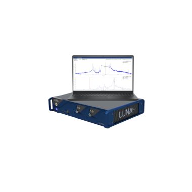

Luna LWA 7601-O Reflectometer/ Lightwave Analyser – O-band

The Luna LWA7601-O is a fast and simple-to-use analyser for passive optical components and modules. The LWA7601-O measures and analyses the Insertion Loss (IL) and Return Loss (RL) distribution, as well as lengths and event locations, working in either reflection or transmission and providing results in the time and frequency (wavelength) domains.
- 10 μm sampling resolution
- Up to 1000 m measurement range in reflection (2000m in transmission)
- 1 Hz scan/acquisition rate
- 1.5pm wavelength accuracy
- 90dB RL dynamic range
The LUNA LWA 7601-O instrument utilises optical frequency domain reflectometry (OFDR) technology to measure backscattered or transmitted light as a function of distance/time (or wavelength).
The extremely high sensitivity and sampling resolution (10 μm) make it an ideal analyser for photonic integrated circuits (PICs) and silicon photonics applications. When combined with the extended measurement range option, up to 1000 m measurement range is achieved, making the testing of fibre networks an easy task.
The LWA 7601-O reduces the cost and complexity of test while increasing throughput by measuring RL, IL and length in reflection or transmission with a single instrument.
Key Features:
- Return loss (RL) and insertion loss (IL) analysis
- Analyse components in reflection and transmission
- Trace distributed RL over the entire optical path length
- Spectral analysis of RL and IL
- Detect and precisely locate reflective events and measure path length (up to 1000 m)
- High speed, resolution and accuracy for optimising production test
- 10μm sampling resolution
- 1 Hz scan/acquisition rate
Applications:
- Spatial RL testing
- Automated IL test and analysis
- Skew measurement with sub-picosecond resolution (e.g. financial datacentres)
- PLCs, waveguide devices, AWGs, ROADMs, etc.
- Filters, couplers, switches, beam splitters, FBGs, specialty fibres
| PARAMETER | SPECIFICATION | UNITS |
| Measurement | LWA 7601-O | |
| Maximum Measurement length | Reflection: 100 / 200 / 500 / 1000 | m |
|
Maximum Measurement length
|
Transmission: 200 / 400 / 1000 / 2000 | m |
|
Sampling resolution (two-point)²
|
10 / 20 / 80 / 80 | µm |
|
Wavelength accuracy³
|
±1.5 | pm |
|
Wavelength resolution (max)³
|
0.02 | pm |
|
Time-of-flight delay accuracy³
|
±0.001 / ±0.001 / ±0.005 / ±0.005 | % |
|
Centre wavelength
|
1566.35 | nm |
|
Wavelength scan range
|
±40 / ±20 / ±5 / ±5 | nm |
|
Measurement time (in continuous mode)
|
~1 (50 m), ~2.1 (100 m) / ~2.3 / ~1.3 / ~2.3 | s |
|
Maximum optical power
|
5 | mW |
|
Return Loss Characteristics (Reflection Mode)
|
||
|
RL dynamic range⁴
|
90 | dB |
|
Total range⁵
|
0 to −140 | dB |
|
Sensitivity⁵
|
−145
|
dB |
|
Resolution⁶
|
0.05 | dB |
|
Accuracy⁶
|
±1 | dB |
|
Insertion Loss Characteristics (Reflection/Transmission)
|
||
|
IL dynamic range, in transmission mode
|
90 | dB |
|
IL dynamic range, in reflection mode⁷
|
20 | dB |
|
Resolution⁸
|
0.05 | dB |
|
Accuracy⁸
|
±0.4 (typical ±0.2) | dB |
|
Physical
|
||
|
Remote Interface
|
SCPI API over TCP/IP | |
|
Optical connector type
|
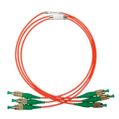
FC/APC
|
|
|
Dimensions
|
35 (L) × 47 (W) × 10 (H) | cm |
|
Weight (controller not included)
|
25 (11.4) | lb (kg) |
2. Distance between two sample points along the length axis in SMF-28.
3. Accuracy guaranteed via internal NIST-traceable HCN gas cell.
4. Range between strongest reflection greater than -60 dB and noise floor.
5. Noise floor return loss at half of maximum length.
6. Measured with 50 cm integration width, and 85 nm wavelength range / 10 THz optical
frequency range
7. Two way loss before backscatter reaches noise floor and IL measurements are no longer
possible.
8. Applies to measurement of the Insertion Loss occurring at a spatially localized event, based
on the difference of the Return Loss of the fiber Rayliegh scatter immediately before and
after the event.
- The IL measurement assumes that the same fiber type is used before and after the
event, so that the same intrinsic fiber Rayleigh scatter level is expected in the absence of
Insertion Loss leading up to tht section of fiber.
- To obtain specified accuracy and given the natural spatial variation of fiber Raleigh
scatter for telecom grade SMF, the spectral range of laser sweep should be at least 10 THz.
- To obtain specified accuracy and given the natural spatial variation of fiber Raleigh
scatter for telecom grade SMF, integration width over which the fiber scatter RL is
determined should be at least 0.5 m in extent.
 LUNA LWA-7601-O Datasheet